1.700 TO 50.0 GHz
|
1.700 TO 50.0 GHz |

CROSSGUIDE DIRECTIONAL COUPLERS
These
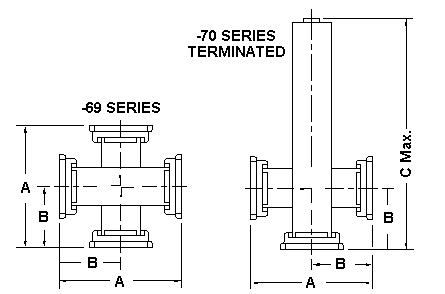
crossguide directional couplers are compact units that contain appropriate
coupling apertures in the broad wall junction. The 69 Series coupler is
used to sample power flowing in both directions. The 70 Series coupler is
used primarily to sample power flowing in one direction. These units have
excellent VSWR, coupling and directivity characteristics.
Crossguide couplers to meet special requirements of coupling, coupling
sensitivity or directivity over limited band widths can be designed by Waveline
upon request. Alternate materials and flanges are available. See
flange section. Finish in instrument gray enamel.
General Specifications:
Coupling........................20, 30, 40, 50 or 60 dB standard (other
values available on special order.)
Minimum Directivity....20 dB (15 dB for 1169 & 1170)
Coupling Sensitivity....Plus or Minimum 1.5 dB maximum over waveguide frequency
range.
Maximum VSWR: (Any Arm) 20 dB Units..1.15
30, 40, 50 & 60 dB Units.....1.10
| WG Size |
Frequency Range, GHz |
Equivalent Flange Type |
WG Mtl. |
Average Coupling |
Inches A |
Inches B |
Inches C Max. |
Model No. |
Model No. |
| WR-430 | 1.70 to 2.60 | CPR-430 Flat | AL | +/- 0.5 dB | 8.50 | 4.25 | 22.25 | 4369 | 4370 |
| WR-284 | 2.60 to 3.95 | UG-584/U Cover | AL | +/- 0.5 dB | 8.00 | 4.00 | 14.78 | 269 | 270 |
| WR-229 | 3.30 to 4.90 | CMR-229 Style | AL | +/- 0.5 dB | 6.00 | 3.00 | 11.59 | 2969 | 2970 |
| WR-187 | 3.95 to 5.85 | UG-407/U Cover | AL | +/- 0.5 dB | 5.00 | 2.50 | 9.34 | 369 | 370 |
| WR-159 | 4.90 to 7.05 | CMR-159 Style | AL | +/- 0.5 dB | 5.00 | 2.50 | 8.65 | 5969 | 5970 |
| WR-137 | 5.85 to 8.20 | UG-441/U Cover | AL | +/- 0.5 dB | 5.00 | 2.50 | 8.03 | 469 | 470 |
| WR-112 | 7.05 to 10.0 | UG-138/U Cover | AL | +/- 0.5 dB | 400 | 2.00 | 6.96 | 569 | 570 |
| WR-102 | 7.00 to 11.0 | WR-102 Cover | AL | +/- 0.5 dB | 4.50 | 2.25 | 7.53 | 0269 | 0270 |
| WR-90 | 8.20 to 12.4 | UG-135/U Cover | AL | +/- 0.5 dB | 3.00 | 1.50 | 5.72 | 669 | 670 |
| WR-75 | 10.0 to 15.0 | WR-75 Cover | AL | +/- 0.5 dB | 3.00 | 1.50 | 5.25 | 7569 | 7570 |
| WR-62 | 12.4 to 18.0 | UG-1665/U Cover | AL | +/- 1.0 dB | 2.50 | 1.25 | 4.76 | *769 | *770 |
| WR-51 | 15.0 to 22.0 | WR-51 Cover | AL | +/- 1.0 dB | 3.00 | 1.50 | 4.97 | 5169 | 5170 |
| WR-42 | 18.0 to 26.5 | UG-595/U Cover | BR | +/- 1. 0 dB | 2.25 | 1.13 | 4.17 | 869 | 870 |
| WR-28 | 26.5 to 40.0 | UG-599/U Cover | BR | +/- 1.0 dB | 2.25 | 1.13 | 3.50 | 1069 | 1070 |
| WR-22 | 33.0 to 50.0 | WR-22 Rd. Cover | BR | +/-1 .0 dB | 1.75 | .88 | 2.94 | 1169 | 1170 |
|
When Ordering: Add dB coupling value to model number i.e., to order WR-90 size terminated 20 dB coupler, specify 670-20. |
| *796-20 and 770-20 Frequency Range 12.4 - 17.5 GHz |
|
52 |
P.O. BOX 718, West Caldwell, NJ (973) 808-9113 Fax (973) 808-1524 |
P | N | T |