1.70 to 50.0 GHz FAIL-SAFE
|
1.70 to 50.0 GHz FAIL-SAFE |

SOLENOID ACTUATED WAVEGUIDE SWITCHES
The
Waveguide series of solenoid actuated switches are lightweight, high quality
devices intended for remote controlled switching applications.
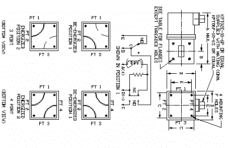
Flange faces on these devices are 90 degrees apart in either the standard
DPDT (4 port) or SPDT (3 part) versions. Standard
77 Series switches are of the fail-safe design, which requires holding current
in position #2 (energized). Removal
of power or a power failure to the drive circuit returns the switch to position
#1 (de-energized).
The switches are made of aluminum*
with balanced rotors and are mounted in high precision ball bearings for rapid
switching and long life. All
standard switches incorporate interlock circuitry to
indicate rotor position or to switch other equipment.
Operating voltage is 28 VDC with low holding current required.
For other voltages or custom features, contact Waveline sales or
engineering. These switches can be
pressurized upon request. Alternate
flanges and materials are available. See
flange section. Finish is
instrument gray enamel.
| General Specifications: | Important Ordering Information: |
| VSWR…………………..1.10 maximum *Isolation……...…………70 dB Voltage…………..……….28 VDC Temperature Range…… -54 Degrees C to +85Degrees C |
Example
677-E-P-SP Basic Model No.-------------| Add -P for Pressure Add -SP for 3 Port Switch |
| WG Size |
Frequency Range, GHz |
Equivalent Flange Type |
Ins. loss dB |
Avg. Power |
Switch Time mS |
Switch Curr. Amps |
Holding Curr. Amps |
Inches A Max. |
Inches B |
Inches C |
Inches D |
Inches E |
Inches F Holes |
Model No. |
| WR-430 | 1.70 to 2.60 | CPR-430 Flat | 0.03 | 20 kW | 500 | 5.0 | 1.0 | 12.00 | 3.625 | 8.000 | 8.00 | 6.500 | #1/2-20 | 4377-E |
| WR-284 | 2.60 to 3.95 | UG-584/U Cover | 0.05 | 15 kW | 200 | 5.0 | 1.0 | 9.37 | 2.781 | 5.875 | 5.00 | 4.500 | #1/4-20 | 277-E |
| WR-229 | 3.30 to 4.90 | CMR-229 Style | 0.05 | 15 kW | 200 | 5.0 | 1.0 | 8.75 | 2.500 | 4.900 | 4.88 | 4.000 | #1/4-20 | 2977-E |
| WR-187 | 3.95 to 5.85 | UG-407/U Cover | 0.05 | 12 kW | 100 | 5.0 | 1.0 | 7.00 | 2.000 | 3.900 | 3.90 | 3.250 | #1/4-20 | 377-E |
| WR-159 | 4.90 to 7.05 | CMR-159 Style | 0.05 | 10 kW | 100 | 5.0 | 1.0 | 6.75 | 1.880 | 3.900 | 3.90 | 3.250 | #1/4-20 | 5977-E |
| WR-137 | 5.85 to 8.20 | UG-441/U Cover | 0.05 | 10 kW | 100 | 5.0 | 1.0 | 6.50 | 1.750 | 3.900 | 3.90 | 3.250 | #1/4-20 | 477-E |
| WR-112 | 7.05 to 10.0 | UG-138/U Cover | 0.05 | 6 kW | 100 | 2.3 | 0.45 | 4.23 | 1.109 | 2.250 | 2.25 | 1.875 | #6-32 | 577-E |
| WR-102 | 7.00 to 11.0 | WR-102 Cover | 0.06 | 5 kW | 100 | 2.3 | 0.45 | 4.53 | 1.156 | 2.375 | 2.25 | 1.750 | #8-32 | 0277-E |
| WR-90 | 8.20 to 12.4 | UG-135/U Cover | 0.07 | 4 kW | 100 | 2.3 | 0.45 | 4.10 | 1.016 | 2.000 | 2.25 | 1.625 | #6-32 | 677E |
| WR-75 | 10.0 to 15.0 | WR-75 Cover | 0.07 | 3 kW | 100 | 2.3 | 0.45 | 3.90 | .900 | 1.800 | 2.25 | 1.375 | #6-32 | 7577-E |
| WR-62 | 12.4 to 18.0 | UG-1665/U Cover | 0.10 | 2 kW | 100 | 2.3 | 0.45 | 3.60 | .812 | 1.625 | 2.25 | 1.280 | #6-32 | 777-E |
| WR-51 | 15.0 to 22.0 | WR-51 Cover | 0.15 | 1.5 kW | 100 | 2.3 | 0.45 | 3.56 | .750 | 1.625 | 2.25 | 1.280 | #6-32 | 5177-E |
| WR-42 | 18.0 to 26.5 | UG-597/U Cover | 0.20 | 750 W | 100 | 2.3 | 0.45 | 3.40 | .626 | 1.500 | 2.25 | 1.125 | #6-32 | 877-E |
| WR-28 | 26.5 to 40.0 | UG-599/U-AL Cover | 0.20 | 400 W | 100 | 2.3 | 0.45 | 3.20 | .532 | 1.500 | 2.25 | 1.125 | #6-32 | 1077-E |
| WR-22 | 33.0 to 50.0 | WR-22 Rd. Cover | 0.30 | 350 W | 100 | 2.3 | 0.45 | 3.75 | .687 | 1.375 | 2.25 | 1.062 | #6-32 | *1177-E |
| *Model No. 1177-E Isolation: 50 dB minimum. Material OFHC Copper |
|
Please call if you need any further assistance or information. |
|
49 |
P.O. BOX 718, West Caldwell, NJ (973) 808-9113 Fax (973) 808-1524 |
P | N | T |